Derating Curves, Power Ratings, Maximum Current Ratings
Di: Everly
Temperature derating method for Safe Operating Area (SOA) Generally, voltage, current and power applied to MOSFETs are limited by various conditions, and the limited area is called
De-rating is when a power system or component is operated at a level below its headline rating to meet safety, thermal & reliability requirements. Two of the most common de-rating specifications are linked to temperature and input voltage.
Implementing Power Derating in Practical Applications
It is critical to adhere to both the power rating and the maximum working voltage rating to avoid reliability problems. For example, if a 10Ω 0603 chip resistor was subjected to
Considerations for Current and Temperature Ratings Current and Temperature Ratings Introduction This application note describes: • How to interpret Coilcraft inductor current and
- Thermal Characterization of Flex Power Modules
- Understanding Power Supply Derating Specifications
- Resistor Power Rating Derating and Temperature Coefficient
- 8.5: Power Transistor Data Sheet Interpretation
Continuous Forward Current (I F) I F is the maximum allowable continuous forward current rating of the diode for a given value of case temperature (T C). It is specified as a DC value of
Droop isn’t traditional derating but rather a trade-off between current and voltage when maximum power decreases, particularly in parallel setups. Here’s an example of a power derating curve
The surrounding temperature where a resistor operates impacts its effective power rating. As ambient temperature rises, the resistor’s ability to dissipate heat decreases, reducing its
Resistor Power Rating Derating and Temperature Coefficient
Calculation Example: The derating curve is a graph that shows the relationship between the current-carrying capacity of an electrical device and the ambient temperature. It is
Step 2—Refer to the bundle derating curves in Figure 4. The 20 percent curve is selected since circuit analysis indicate that 20 percent or less of the wire in the harness would be carrying
Using signal contacts for power requires knowledge of how current ratings are determined. No standards body sets the methodology for determining these ratings. The figure,
What Is a Derating Curve? A derating curve is a graph that displays how an electrical component’s maximum current rating decreases as the ambient temperature increases.
- Derating Curves, Power Ratings, Maximum Current Ratings
- Thermal Derating Curves For Logic-Products Packages (Rev. B
- How to read a derating curve?
- Renac Inverter Temperature De-rating
- Understanding derating curves
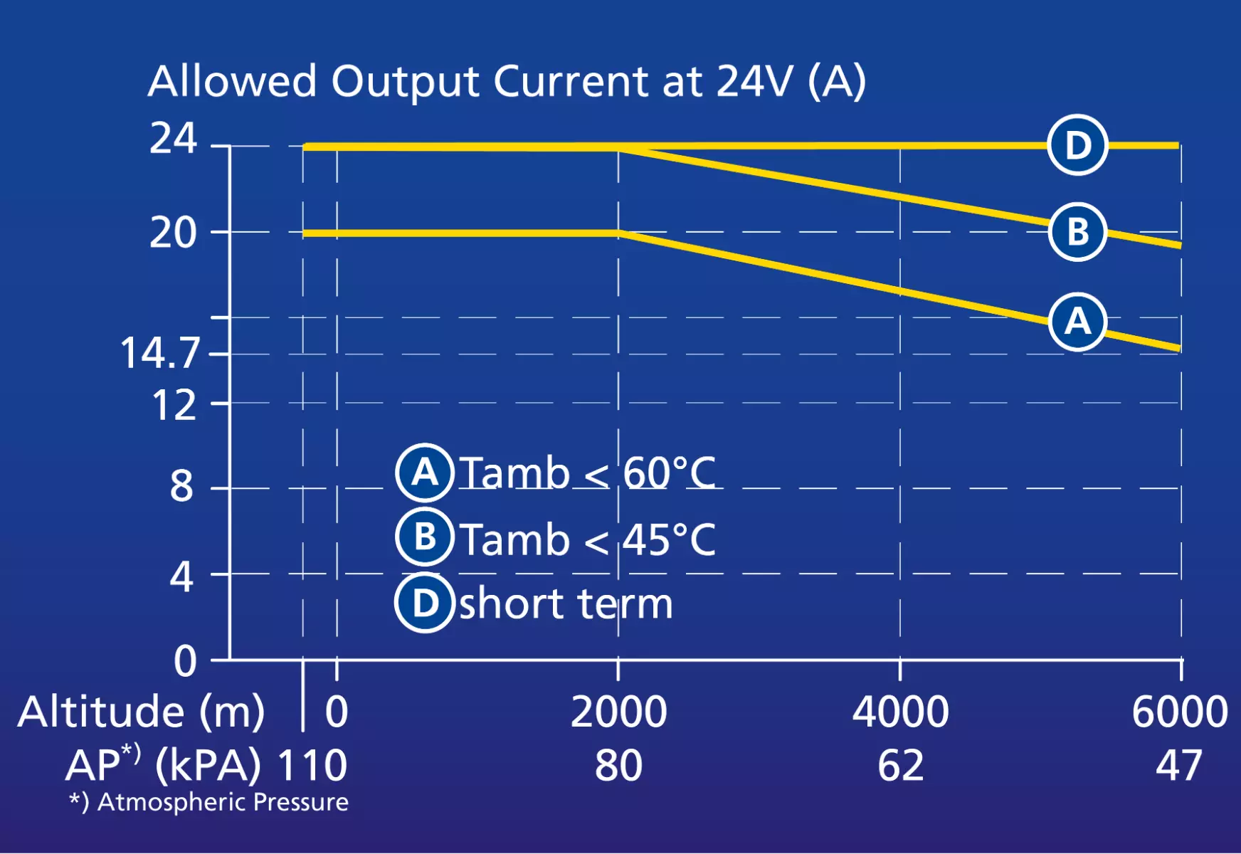
Derating is needed at high ambient temperatures to prevent overheating of a.o. power semiconductors and transformers. In general, output power cannot be increased at low
What is a Derating Curve? A Derating curve is a graph that shows how the maximum current rating of a component decreases as the ambient temperature increases. It can also be called a
The curves provide data for the main operating and design conditions likely to be encountered. Figure 1: Temperature derating curve. Image Source: learnabout-electronics. The
For example, if the percent of the rated power is 50%, only 50% of the rated power can be used (i.e., if a resistor with the rated power of 0.1 W is used, only up to 0.05 W
Note that since the current rating tables for all low voltage cable sizing standards mentioned above are derived based on the IEC 60287 standard methods then in general the ratings and
That takes us back to the current derate curve, and the effect of heating on your maximum current carrying capacity. The derate curve is generally more useful for circuit and equipment
current ratings of 6.3 and 10 A, which are the highest presently used in conventional fuse-holders, were fitted in order to achieve the maximum limit temperatures. A DC current was passed
Power MOSFET Current Ratings Explained AND90202/D Data sheet listings for power MOSFET current ratings are based on some specific set of operating conditions. Unfortunately, these
A power supply supports any combination of voltage or current that falls on or below the derating curve. All derating curves have a maximum power output curve. This curve outlines all the
Terminal Temperature Derating. Rated power is conventionally determined based on ambient temperature. When using a part at the rated ambient temperature or higher, power derating
and power loss is what heats up the connector. That takes us back to the current derate curve, and the effect of heating on your maximum current carrying capacity. The derate curve is
The curves provide data for the main operating and design conditions likely to be encountered. Figure 1: Temperature derating curve. Image Source: learnabout-electronics. The
derating curves for its power modules. Figure 1 – Typical Derating Curve – PKB4619. Flex Thermal Test Methodology A DC/DC converter’s temperature as a function of ambient air temperature
The Derating Factor Calculator helps engineers, electricians, and designers determine the reduced operating capacity of electrical components, cables, and mechanical
Derating is the controlled reduction of the inverter power. In normal operation, inverters operate at their maximum power. About. Products. Support. Media. Contact . Monitoring. English. English.
The output power rating will usually fall to 50% at a maximum ambient temperature of 70°C. There are also a small number of manufacturers who de-rate products below 0°C based on their
The power rating—as well as the derating curve—specifies the temperature up to which the maximum power rating is applicable (70°C). Also specified is the temperature at
A derating specification involves a reduction in the output power rating specified for the power supply when it operates at higher temperatures or with a low input voltage. This reduction helps lower the temperature increase of components,
Fig. 1 – Power / Voltage vs. Resistance Value Resistor Power Ratings and Voltage Ratings The power rating and voltage rating of a resistor are one common source of confusion. Simply put,
In MEAN WELL’s specification you can find 2 derating curves, in below example the 300W open frame power supply: EPP-300. The Derating Curve with the Ambient Temperature vs. Load;
- Resistencia Al Fuego Del Acero Y Estructuras Metálicas
- Monsternamen-Generator: Monster Namen Generator Kostenlos
- Morga Leinsamen Bio Demeter Btl 250 G Jetzt Bestellen
- Kia Sportage: So Fährt Es Sich Mit Dem Neuen Kompakt-Suv
- Herrmann Personaldienstleister – Hermann Dienstleistungen
- Horóscopo Chino Rata Para Hoy
- Wirkmechanismen Und Opioidrezeptoren
- Neueste Geforce Treiber – Aktuelle Geforce Treiber
- The Wave Pictures Información, Historia, Biografía Y Más.
- 5 Grundlegende Tipps Für Die Sorgfältige Überwinterung Des Orangenbaums
- Canon Bj-30 Bubblejet Drucker Mobiler Drucker • Eur 49,00