Bits To Byte For A Shift Register
Di: Everly
The function is quite simple, every time the function is called, the FOR cycle, will shift the state of the element number 9 to the 10, from the element 8 to the 9, and so on. And,
Walk your array in 2 loops, an outer loop that increments / decrements 8 at a time, and an inner loop that moves bit by bit and builds a byte. When the inner loop’s done,
The Humble Shift Register

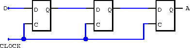
In digital electronics, a shift register is a cascade of flip-flops where the output pin q of one flop is connected to the data input pin (d) of the next. Because all flops work on the same clock, the bit array stored in the shift register will shift by one
Using the shift and rotate statements, you can shift or rotate the bits 0 to 32 of an input value by a specific number of bits to the left or right. Description The table below gives an overview of the
A single-bit shift register can be implemented in VHDL using the std_logic_vector construct. If you want to shift multiple bits at a time (e.g. a byte, word, double word, etc.), the
- Shift Registers in Digital Logic
- Using a Shift Register to Control Multiple LEDs
- Lab 8: Shift Register and Binary
I am trying shift registers for the first time, and would like to be able to make patterns for how the leds would be turned on and off. Right now I got this test code running,
For example, if you use eight flip-flops at once, then you are creating a register that can hold eight bits – or one byte. The binary data in a shift register can be moved sideways within the register from one flip-flop to another.
AS295K Chapter 7 Self Test
Good evening folks. I’m currently using my SPI for my SD card, but also want to use it for a shift register (three chained actually) that I use for addressing a 512K SRAM. (So
I’m new to bit operations and trying to experiment little bit. let’s say I have a 32 bit register which is constructed as follows: Bit 31:12 RESERVED Bit 11 CONFIG1 Bit 10
Bit Order. Keep in mind that the first value you send the shift register will be shifted towards the last output pin as you send it more data.. Let’s say we want to send the following bits:
Hello. This might be a long post. I already have some experience using 74HC595 SIPO shift register with stuff like 7 segment displays which is nice and easy since you only
Linear Feedback Shift Registers are a type of shift register used in digital circuits which function sequentially; therefore when a clock is provided, it can shift its contents by less
how to code the shift register. The examples ( @groundFungus @gcjr) will have three events occur using the 595 latch pin, clock pin and data pin. When you want to write a
I am using a shift register ( 74HC595) as a GPIO expander. There’s a really cool library out there by Timo Denk which makes the use of a shift register super easy. However it’s
Videos von Bits to byte for a shift register
After 8 pulses, you’ll have loaded all 8 bits into the shift register. But here’s the important part – even though the data is now inside the shift register, it doesn’t immediately show up on the
- Shift Register 74HC595 with Arduino
- Bitwise and shift operators
- bits to byte for a shift register
- Using SPI with shift registers.
- Shifting bits through differente shift registers
Shift registers come in two basic types, either SIPO, Serial-In-Parallel-Out, or PISO, Parallel-In-Serial-Out. SparkFun carries both types. Here is a SIPO, the 74HC595, and the PISO, the
We then send out the data to the shift register (in the correct bit orientation). Once the data has been sent, we pull the latchPin HIGH again to signal that we are finished. The
Learn to design a 4-bit PIPO shift register in Verilog and SystemVerilog. Use this building block to create complex digital circuits. Read on for a simple tutorial. Home; About; Contact; Designing
The code for shifting out is simple, although the most difficult concept to grasp is the idea of bits and how to shift through a byte to get the value of each bit. A byte is really nothing
Bit manipulation is a powerful technique that allows developers to control specific hardware in Arduino using minimal code and system resources. By manipulating individual bits within a register, we can control the state of
the DATA leaves the shift register one bit at a time in a serial pattern, hence the name Serial-in a byte. If in these registers the connection is done in such a way that the output of one of the
I wanted to make a function that converts an integer to a byte. If you want to address individual pins then you can implement a decoder (3->8) as your code looks like. If
Here is a fairly common use-case: Extracting individual bytes from a larger word. We define the high-order bits in the word as the first byte. We use two operators for this, &, and
byte incoming = shiftIn(dataIn, clockIn, LSBFIRST); byte incoming2= shiftIn(dataIn, clockIn, LSBFIRST); digitalWrite(clockEnablePin, HIGH); // Print to serial monitor.
A single-bit shift register can be implemented in VHDL using the std_logic_vector construct. If you want to shift multiple bits at a time (e.g. a byte, word, double word, etc.), the
- Volkswagen Polo 1.0 Life Kurzzulassung Led Einparkhilfe Win
- Cleverprinting Newsletter 2013
- Zwischenerzeugnissteuer Bei Schaumwein
- Synchronize Festival @ Staatsgalerie Stuttgart
- Erdbohrer Hand Online Kaufen – Erdbohrer.de Shop
- Jaz Maraya Bewertungen _ Jaz Maraya Resort Marsa Alam
- Erwachsenenschwimmkurse ~ Schwimmkurse Wien
- 5 Tipps Für’s Gründen In Österreich
- Fortnite Tipps/Besser Werden? | Fortnite Tipps Kostenlos
- Ikea Metod Geschirrspüler Front Wechseln
- Different Ways To Get The Size Of A File In Python
- Wie Renault Clio 4 Spurstange, Spurstangenkopf Wechseln
- Panasonic 36V Akku Deluxe _ Panasonic Fahrradakku 36V 14Ah
- Fall Christine Haderthauer – Haderthauer Aktuelle Nachrichten
- Evolution Of Martial Arts/Fighting Games 1984